31+ flat pattern drawing solidworks
I think we should put a note under the flat pattern view that indicates this flat pattern shouldnt necessarily be construed as 11. For example in Fig2 you can see that the part length in the isometric view is 200 mm while the flat.

Pin On Solidworks
Click Make Drawing from PartAssembly Standard toolbar and click OK to open the drawing sheet.
. Did you make a configuration. Select a format or click OK to use the default format. Provided Ive inserted this as a Flat Pattern View either from my Drawing View Palette or from the Insert Views menu I will have this option in the Property Manager that pane on the left side of the screen that lets me control the properties for just about everything in SolidWorks.
Unlike the Formed manufacturing method. The advantages are huge and clear you can design all your sheet metal components in the context of one part generate a handy cut-list and sprinkle the drawings with nice balloons like in assemblies. Go to the SolidWorks drawing the flat pattern doesnt update even if the drawing is rebuilt.
Wrong flat pattern in View Palette. Open the sheet metal part for which you want to add a drawing. Switch back to the drawing.
When a flat pattern view is inserted into a drawing either from the View Pallette or the Model View Property Manager a Derived Configuration gets automatically created in the Sheet Metal part. Automatic scaled flat pattern view. From the View Palette drag the Flat pattern to the drawing sheet.
After saving this document the customer has reopened the drawing in SOLIDWORKS and found that the flat pattern view is no longer showing in the flattened state and we have some dangling dimensions. Click the Flatten button in the Sheet Metal toolbar so that the part bends back up. Only works with a Flat Pattern view.
I think I will have the dimensions across bends removed from the flat pattern view on our drawing as it just seems to open a can of worms. Creating Drawings of Flat Patterns. In most cases this is what youre looking to work with because you want to use the smallest blank when cutting out your flat pattern prior to bending it.
So the programs are incorrect. When the Flat-Pattern drawing view of a SOLIDWORKS sheet metal part displays the part in the bent configuration this often indicates an issue with the suppression state of the Flat-Pattern feature in the part file. From the View Palette drag the Flat pattern to the drawing sheet.
Open up the part modify a dimension or two rebuild. However our CNC programming software is designed to open a part flatten it and close all SW files. If I open the drawing first I get a correct formed view but the hole spacing is incorrect on the flat pattern view.
Set the active configuration to DefaultSM-FLAT-PATTERN. I still wonder about the 11 scale on the drawing. Creating flat pattern template.
Click Make Drawing from PartAssembly Standard toolbar and click OK to open the drawing sheet. SOLIDWORKS has supported sheet metal multi-body parts for the last two releases but that still came as a pleasant surprise for me. -Deleted the flat pattern configuration and then reinserted the view to make Solidworks make the flat pattern into the drawing-Closed restarted Solidworks-Restarted my computer.
Click Make Drawing from PartAssembly Standard toolbar and click OK to open the drawing sheet. I want to use the task scheduler and my template to fill out the folder with desired drawings but I cant seem to make the solidworks template work with Flat Pattern. Select a format or click OK to use the default format.
Open the sheet metal part for which you want to add a drawing. From the View Palette drag the Flat pattern to the drawing sheet. To create a drawing of a flat pattern.
It simply is not offered in. Drew finds the sheet metal part and its flattened. Until now Drew could not really handle these flat patterns.
In your drawing you need to switch it to flat pattern if you have a configuration which you should for your flat pattern. When SolidWorks generates a flat pattern of a sheet metal part it solves for the smallest rectangular bounding box that can contain the flat geometry of the part. To create a drawing of a flat pattern.
Not showing full flat pattern in drawing mode. Hello fellow SolidUsers Ive been wondering if there is a way to create template in which Flat Pattern is being used. The picture below shows the Reference Configuration for the drawing view selected is DefaultSM-FLAT-PATTERN.
I attached a zip file that contains the drawing and model of the part I am having the problem with. Open the sheet metal part for which you want to add a drawing. Having a scaled flat pattern view on these drawings is really useful.
So in the end I am no sure what to do. If I have the assembly open first and then open the drawing file everything updates fine. And is the preferred method to create lofted bends if you require flat pattern and bend line accuracy.
Select a format or click OK to use the default format. When you create a flat pattern drawing view the system automatically creates a flatten derived configuration Fig. As shown in the figure below the Flat Pattern view is the same as the front view and shows the part in a bent state.
1 This means that there could be circumstances where the default and derived configurations are out of sync with each other. When functioning normally this derived configuration SHOULD have the flat pattern feature unsuppressed in the parts feature tree however it is easy to accidentally suppressunflatten it. As you can see the view is still set to the Flat pattern Orientation in the Drawing View PropertyManager but the drawing view is no longer flattened.
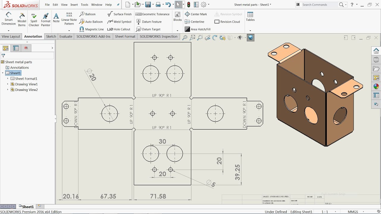
Its a drawing of a sheet metal part with 3 orthographic views in the folded state and a flat pattern view. To understand what happens to flat pattern views in drawings you need to know a little bit about what that flat pattern view does. This will happen if the SM-FLAT-PATTERN sub-configuration of your model has been activated then made to be folded.
Whenever you insert a sheet metal part into a drawing SOLIDWORKS automatically creates a derived configuration in the part file for the flat pattern. Many of our users create sheet metal parts and create drawings for those parts. Now when you click the Add button this happens.
When the Flat pattern drawing view of a SolidWorks sheet metal part displays the part in the bent condition this can indicate an issue with the suppression state of the Flat-pattern feature. Have a sheet metal part and cooresponding flat pattern drawing.

Sheet Metal Drawing Sheet Sheet Metal Drawing Drawing Sheet Sheet Metal

Pin On Sheet Metal
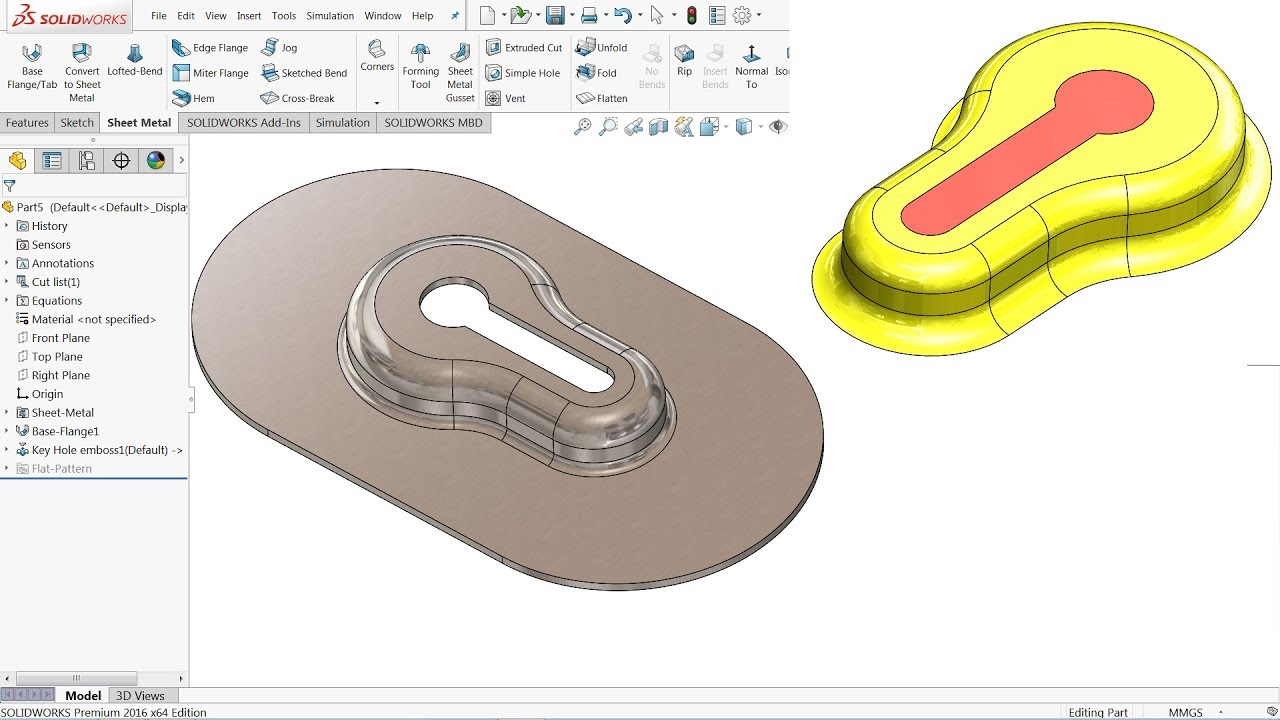
How To Make Custom Forming Tool In Solidworks Sheet Metal Youtube Solidworks Solidworks Tutorial Sheet Metal

Pin On Solidwork

Pin On Solidworks

Solidworks Sheet Metal Tutorial Forming Tool Youtube Solidworks Tutorial Solidworks Sheet Metal

Solidworks Sheet Metal Tutorial Calculate Flat Form Of Elbow In Solidworks Youtube Sheet Metal Sheet Metal Drawing Sheet Metal Fabrication
Solidworks Tutorial Sheet Metal Drawings Youtube Sheet Metal Drawing Solidworks Tutorial Solidworks

Pin On Solidworks

Solidworks Sheet Metal Exercise 129 Sketched Bend And Jog Youtube Solidworks Sheet Metal Drawing Exercise Sheets

Pin On Solidworks

Pin On Drafting Cadd

Electrical Box Flat Pattern Drawing Sheet Sheet Metal Drawing Drawing Sheet Sheet Metal

Display Sheet Metal Bend Notes 1 By Inserting The Flat Pattern Configuration Into The Drawing As A Regular View Solidworks Property Management Flats Patterns

Pin On Melc